
This post is a more detailed explanation of our previous post about STP. This is quite a complicated topic that also requires a deeper understanding of what causes a switching loop. I assume that you have already read it, so let’s get started.
First, see the image below as an illustration.
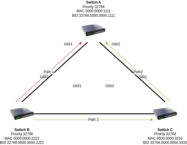
A root switch selection process is triggered when the switches come up for the first time. As multiple switches are involved, and there is only one root bridge, the selection of the switch as a root bridge is based on the switch Bridge ID (BID). BID itself is an 8-byte field consisting of two parts, 2-byte bridge priority (default = 32768) and 8-byte switch MAC Address.
Let’s take an example from the above diagram.
At first, each switch declares itself as a root bridge. When connected, each
of them will send a Hello BPDU (Bridge Protocol Data Unit) packet.
Here is a brief explanation of BPDU.
In the Hello BPDU frame format, there is a section called IEEE BPDU which
contains fields that are important for STP.
Protocol ID (2 bytes)| Ver. (1 byte)| Msg Type (1 byte)| Flags (1 byte)| Root
ID (8 bytes)| Root path cost (4 bytes)| Bridge ID (8 bytes)| Port ID (2
bytes)| Message age (2 bytes)| Max. age (2 bytes)| Hello time (2 bytes)|
Forward delay (2 bytes)
---|---|---|---|---|---|---|---|---|---|---|---
Let’s focus on only three fields, the Root ID, Root path cost, and Bridge ID.
- Root ID is the ID of the root bridge. In case of the sender’s switch becoming the root bridge, it will be the same as bridge ID.
- Root path cost is the cost needed by the sender to reach the root bridge.
- Bridge ID is the sender’s BID.
Because each switch declares itself as a root bridge, they will have three fields filled with something like this.
| Root ID | Root path cost | Bridge ID | | -------- | -------------------- | --------- | -------------------- | | Switch A | 32768.0000.0000.1111 | 0 | 32768.0000.0000.1111 | | Switch B | 32768.0000.0000.2222 | 0 | 32768.0000.0000.2222 | | Switch C | 32768.0000.0000.3333 | 0 | 32768.0000.0000.3333 |
Root ID is identical with Bridge ID for the reason we already know, the switches declare themselves as root bridge. Because they think that way, the root path cost is set to zero for the same reason, so no cost needed to reach them. However, only a single switch can be a root bridge.
As each switch has a BID, all interconnected switches will exchange their BIDs. Now, the switches have BPDU of each other and therefore compare it. They decide which one has the lower BID value to set as a root bridge.
Switch A
Because we know that the BID contains of two parts, which is basically bridge priority + switch MAC address, the switch A (BID 32768.0000.0000.1111) is superior to both switch B (BID 32768.0000.0000.2222) and switch C (BID 32768.0000.0000.3333). Thus, switch A is the root bridge. Switch A will declare itself as a root bridge after receiving Hello BPDU from B and C by comparing its BID with theirs. At this point, the root path cost is still 0.
Switch B
If switch B only receives Hello BPDU from C, it won’t change its root ID field with switch C’s BID. In fact, it also receives Hello BPDU from A to and therefore modifies its root ID field to switch A’s BID. Because it is no longer a root bridge, the root path cost will be set to something like 4 in order to reach the root bridge.
Switch C
When C receives the Hello BPDU from both switches and then compares the BIDs, it will consider its BID as inferior, so it will change the root ID to switch A’s BID and change the root path cost to 4. If in another case, all the switch still has the same BID, but say that switch C has priority field of 32765 (which is lower than the rest), the C will be the root bridge instead.
At last, the Hello BPDU will be exchanged again to decide the switch A as a root bridge. After that, path cost will be calculated and ports’ role will be determined whether it becomes a root port , designated port , or blocked port.
If you want to set up the root bridge manually, the best practice is to choose the most centralized switch as a root bridge. To do this, we can set the root bridge priority to a lower number (see the switch C section) so it will be prioritized.
How is the root path cost calculated?
Since we use IEEE 802.1D, which is an IEEE media access control (MAC) bridge standard that includes spanning tree protocol (STP) and bridges, we use the following specification to calculate the path cost.
| Link speed | Cost | Interface Type |
|---|---|---|
| 10 Gbps | 2 | Ten Gigabit Ethernet (Te) |
| 1 Gbps | 4 | Gigabit Ethernet (Gi) |
| 100 Mbps | 19 | Fast Ethernet (Fa) |
| 10 Mbps | 100 | (Ethernet) |
Root path costs are calculated by adding all the costs along the path from the switch to the root bridge. Take an example from the above, we have switch A as the root bridge. How much cost is needed from Switch B to reach the root bridge?
From switch B we have two different paths, path 1 and path 2. To reach the switch A through path 1, we need 4. Otherwise, if the second path is taken, the root path cost would be 4 (switch B to switch C) and 4 (switch C to switch A). Thus, path 2 will need 8 (4+4) which is more costly than path 1. Because path 1 has lower root path cost, this port is preferred and will be set as a root port. In contrast, path 2 will be set as the blocked port.
At this point, you might also notice that the faster the link speed the more likely it is to be set as the root port. In other words, it is based on the link bandwidth. It is “cheaper” to travel along a path with higher bandwidth.
Port roles
Previously it was explained that after carrying out the root path cost calculation, the role of each port will be assigned. The following is an explanation of these roles.
- Root port is the port that has the lowest cost to the root bridge (the best port).
- Designated port is the destination port.
- Blocked port is a port that is in a blocking state.
In more complex cases, a non-root switch may have multiple designated ports, but it may only have one root port. On the other hand, the root bridge as the destination switch, certainly will only have designated ports.
Thus, if we take the example above, then
| Switch A | Switch B | Switch C | | -------- | --------------- | --------------- | ------------ | | Gi0/1 | Designated port | Designated port | Root port | | Gi0/2 | Designated port | Root port | Blocked port |
In this case the blocked port is on switch C and not on switch B. Switch B has a lower BID than switch C, thus selected as designated port. Due to the blocked port blocking state, it will still receive the frame, but will not send it and simply drops it.
State
The switch port can be in one of these five different states.
Disabled (DIS)
The port is currently shut down.
Block (BLK)
In this state the Hello BPDU message will still be received. However, the port won’t send nor forward it. In the event that another link fails, the spanning tree algorithm may change this to forwarding state. The blocking state plays an important role in preventing the loop.
Listening (LIS)
The port is awaiting new information. It will not forward the frame nor populate the MAC address.
Learning (LRN)
The state populates and learns the MAC address, but does not forward the frame.
Forwarding (FWD)
Port actively receiving and sending the information.
It is also important to note that the forward delay (see Hello BPDU frame format) indicates how long it takes for the port before transitioning to the new state with a default value of 15 seconds.
How does the port state change?
When not attached, the port will be in DIS state and changed to BLK in order to prevent loops. When the forward delay expires, the port enters the LIS state, waiting for Hello BPDU. Again, after the forward delay express, the port enters the LRN state, in order to collect MAC addresses from the frames and store them in the switching database. Once more, it will wait for the forward delay and determine whether ports will enter FWD state or BLK state.
Still using the example, the end state would be like the following.
| Switch A | Switch B | Switch C | | -------- | -------- | -------- | --- | | Gi0/1 | FWD | FWD | FWD | | Gi0/2 | FWD | FWD | BLK |
Conclusion
We have learned how STP works in detail. We have seen how switches communicate with each other using Hello BPDU packets and how they select a root bridge based on the lowest BID. We have also learned how to calculate the root path cost and how to assign port roles and states. We have understood the importance of STP in preventing switching loops and ensuring network stability. We hope this article has helped you to master STP and optimize your network performance.