
A switch is a networking device that works on layer 2 in the OSI model which makes it possible for devices or access points to communicate with each other by exchanging data packets. In an office, it is common to see multiple switches being employed in the network.
Isn’t using multiple switches at once redundant? Well, you might be right. However, it gives its own advantage in case the link is broken down or fails. Since another link is still available to let the devices keep connected. However, setting up multiple switches properly is not as easy as it seems.
Before going deeper into this topic, it will be easier to understand if you know how the switch works. In a simple manner, the switch is used to let the message be sent to the intended recipient. Say that you have four devices, PC 1, PC 2, PC 3, PC 4 connected to a single switch.
In the case that PC 1 wants to send a message to PC 4 it can send the data exclusively to PC 4 without letting PC 2 and PC 3 know. Thus, establish one- to-one conversation. In order to do this, the switch needs to identify each device. Once a device is connected to the switch, it will identify the device by its MAC address. This MAC address will then be stored in a table called MAC address table.
Not only that, the switch can also be a facilitator for the broadcast domain. It makes it possible for a single device to send a message to all the devices connected to the same switch or network. Just like the one-to-one conversation, the switch will check the registered devices by using the MAC address table.
Problem
What if we change it with another switch instead of a device?
In a local network, there is something known as a “layer 2 switching loop”. This is the common problem that you need to solve if you want to interconnect multiple switches. Let’s see what it is all about by checking out this real world scenario.
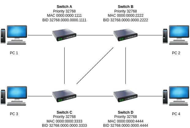
Let’s say you are working with four different switches in order to facilitate more devices to the same network and call it switch A, B, C and D. When you try to link them together, you will find the frame packet transmission going endlessly among the switches. So, why does it happen?
See the diagram below.
Before outlining what happened, it is important to know this concept.
“Broadcast message will send the broadcast packet to all directly connected devices except the originator device itself.”
We assume that PC 1 wants to communicate with PC 4. So the frame transmission will be going like this.
- PC 1 sends the data frame packet to switch A (PC 1 to A).
- Switch A needs to identify all connected devices to check whether the intended is on the list or not by checking its MAC address table. Referring to the diagram, we have no direct access to the intended recipient as the device is not attached directly to the switch physical port. So, the packet will be forwarded to both switch B (A to B) and switch C (A to C). The broadcast works by transmitting the packet to all connected ports except the source port.
- Both will receive the same frame packet that basically asks if the intended recipient is on the list on switch B and switch C MAC address table. The same case happens to both switches and both B and C that will forward the same packet to D (B to D and C to D). Here we get the first problem, the duplicate frame. Other than that, the broadcast will also be forwarded to PC 2 (B to PC 2) and PC 3 (C to PC 3).
- Since we get the duplicate frame on switch D, both frames are then forwarded to the PC 4 (D to PC 4).
- At the same time, because B and C are directly connected, switch B will forward the frame to C and vice versa. Since we have a new source port now (B to C or C to B), the same broadcast packet from switch B will be forwarded again to A (B to A), D (B to D), and PC 2 (B to PC 2). The same way happens for switch C where the same frame will be sent again to A (C to A), D (C to D), and PC 3 (C to PC 3).
- Focusing on switch A, we can find something that is not supposed to happen. PC 1 as the originator, will receive its own broadcast packet. We also get A to C link as source port and the frame will be forwarded to switch B (A to B) which is basically going all over again just like at the beginning of the whole process.
- If you continue, it will be going over and over creating the loop as we send the same frame endlessly. Here goes our second problem known as the switching loop. You will also end up getting the PC 4 receiving even more duplicated frames.
- The loop will go on and on, where single frame packets accumulate uncontrollably creating what we call now as the broadcast storm.
Solution
Actually, it is pretty simple to prevent this from happening. Referring to the concept stated above, we can block certain links so the traffic goes on another only.
For example, in the same scenario and focusing on switch A, we can block the access from A to C. Thus, the frame will then be going to B (A to B). If we don’t block any access on switch B, the frame will be going to switch D indirectly (B to C to D) and directly (B to D). Despite the switching loop not occurring as we want it, the endpoint (PC 4) will still end up receiving the duplicate frames. Therefore, we can also block a single link (for example, B to C) so the packet will be going from PC 1 to A to B to D to PC 4. In this case, we have yet to consider the weight to decide which link is the most efficient route to the intended recipient.
This is the basic idea of how the STP (Spanning Tree Protocol) works. To take it simply, STP is the protocol that blocks one or several ports in order to prevent switching loops and use the blocked ports route as a backup in case the main link fails.
Conclusion
Switches are useful devices that allow communication between multiple devices
or access points in a network. However, when multiple switches are
interconnected, they can create switching loops that cause endless
transmission of data packets and degrade network performance. To avoid this
problem, STP (Spanning Tree Protocol) can be used to block certain ports and
prevent loops, while ensuring efficient routing of data and backup links in
case of failure.